Wire Routing
Wire routing mode provides CAD-style click-to-click drawing. Instead of freehand painting, you click an anchor point and then click a destination — the editor calculates a clean routed path between the two points.
Wire routing works with the Pencil Tool (single wire) and the Brush Tool (multi-wire bus). It also supports Track and Platform paint modes — tracks use thin diagonal routing, and platforms automatically apply proper stair frames (treads, stringers, landings) on 45° miter paths.
Entering Wire Mode
| Shortcut | Action |
|---|---|
Shift+W | Cycle wire mode: Off → 90° Elbow → 45° Miter → Off |
Shift+Q | Cycle direction override: Auto → Horizontal-first → Vertical-first → Auto |
Escape | Cancel current anchor (stays in wire mode) or exit wire mode entirely |
Wire routing works when Wire, Track, or Platform paint mode is selected. The route panel in the action bar shows the current routing mode and direction. The status bar displays the active mode.
Wire Color Shortcuts
While in wire paint mode, press a number key to toggle the corresponding wire color:
| Key | Wire Color |
|---|---|
1 | Red |
2 | Blue |
3 | Green |
4 | Yellow |
These shortcuts are always active in wire paint mode, whether or not wire routing is enabled.
Single Wire Routing (Pencil Tool)
Select the Pencil Tool [E] and enter wire mode with Shift+W.
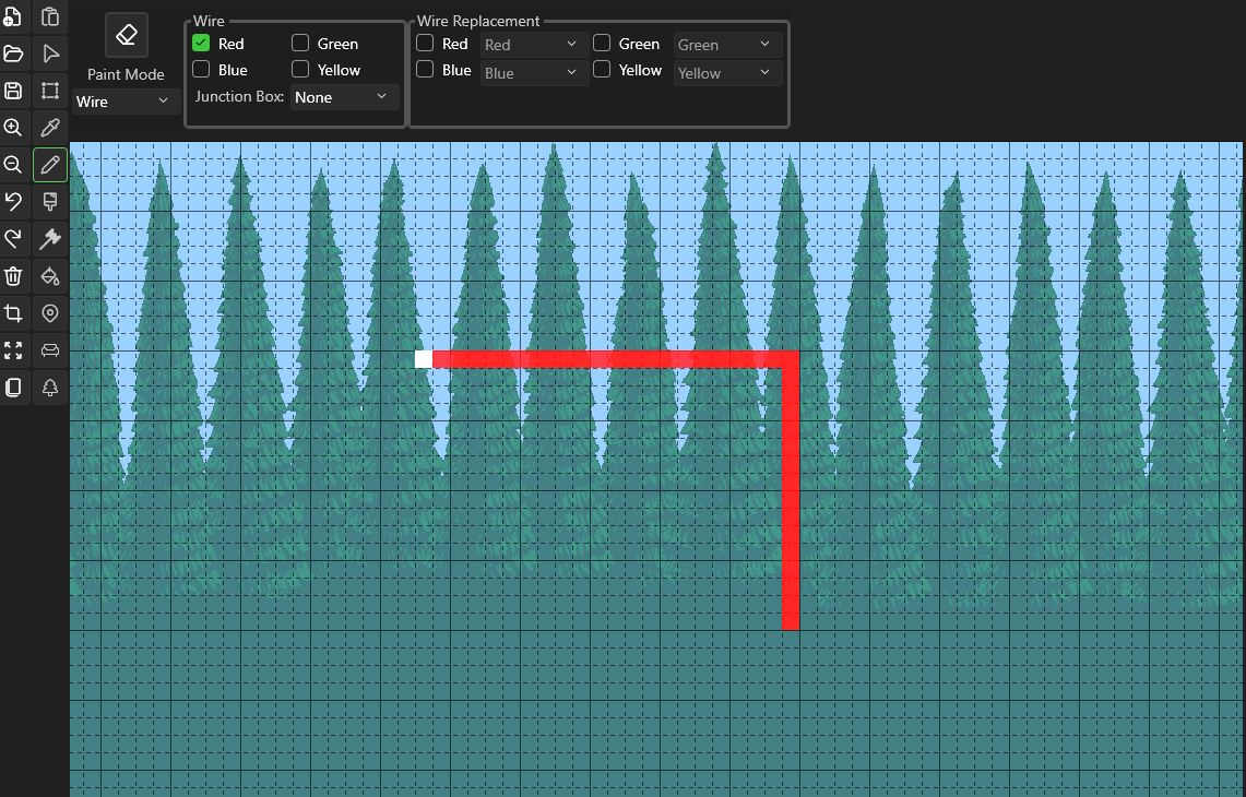
- First click — Sets the anchor point (shown as a bright marker)
- Move the mouse — A preview path appears showing the routed wire
- Second click — Commits the wire and chains the anchor to the new endpoint
- Right-click — Cancels the current anchor without committing
The anchor chains automatically: after committing a segment, the endpoint becomes the new anchor for the next segment. This lets you draw polyline wire runs with precise corners.
Chain Mode

When chain mode is enabled (toggle with Shift+W), each committed segment's endpoint becomes the anchor for the next segment — creating a continuous polyline of routed wire. Disable chain mode to commit single segments that don't auto-anchor.
Chain mode works with both single wire (Pencil) and bus (Brush) routing.
Routing Modes
| Mode | Path Shape | Description |
|---|---|---|
| 90° Elbow | L-shaped | Straight run on one axis, then a 90° turn to the destination |
| 45° Miter | Straight–diagonal–straight | Straight run, staircase diagonal section, then straight run to destination |
All paths are 4-connected — every tile shares an edge with its neighbor (no diagonal-only connections). This ensures wires function correctly in Terraria.
Direction Override
The direction override (Shift+Q) controls which axis runs first:
| Setting | Behavior |
|---|---|
| Auto | Picks vertical-first when the angle is steeper than 45°, horizontal-first otherwise |
Horizontal-first ↔ | Horizontal leg first, then vertical |
Vertical-first ↕ | Vertical leg first, then horizontal |
Bus Routing (Brush Tool)
Select the Brush Tool [B], set a brush size larger than 1×1, and enter wire mode with Shift+W.
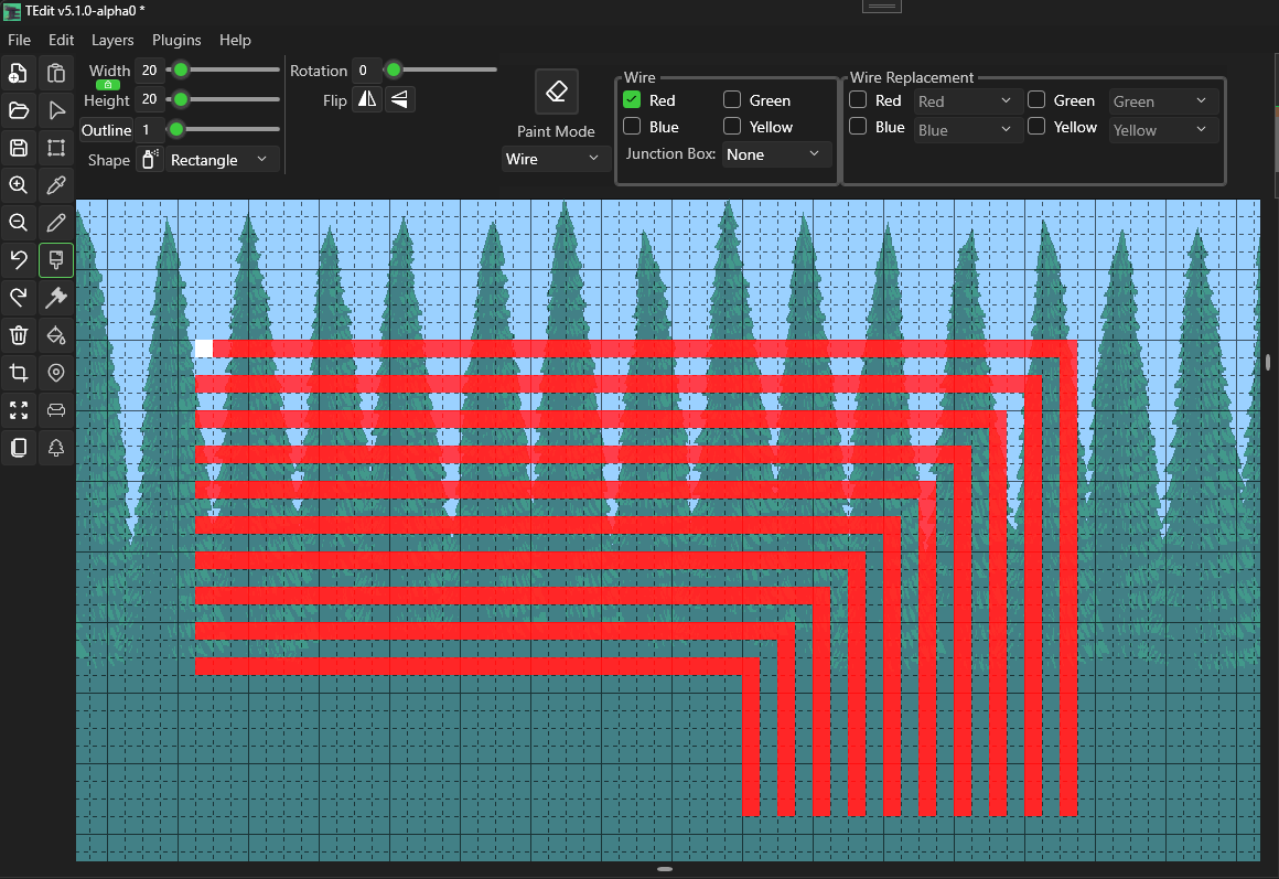
Bus routing draws multiple parallel wires that fill the brush area. The number of wires and their spacing are calculated from the brush width and height.
- First click — Sets the bus anchor at the brush center
- Move the mouse — Preview shows all parallel wire paths
- Second click — Commits all wires and chains the anchor
Wire Spacing
Both 90° elbow and 45° miter bus routing use 2-tile spacing (1-tile gap between wires). Diagonal-touching wires don't connect in Terraria, so miter staircase patterns don't need extra spacing.
Bus Layout
- Wire count is determined by the brush dimensions and spacing
- Wires are centered within the brush area
- Start positions are placed at the opposite edge of the brush from the movement direction
- End positions are spread along the perpendicular axis at the destination, ensuring no two wires overlap or cross at turns
- A 1×1 brush falls through to single-wire routing, identical to the Pencil tool
Use the direction override (Shift+Q) to control whether bus wires run horizontally or vertically first. This determines which edge of the brush the wires start from and which edge they arrive at.
Track & Platform Routing
Wire routing extends to Track and Platform paint modes. The route panel in the action bar is visible for all three modes.
Track Routing
Track mode uses thin diagonal routing for 45° miter paths — each diagonal step occupies a single tile instead of the 2-tile staircase pattern used by wires. When Tunnel sub-mode is active, the preview shows the tunnel clearing area in a darker overlay above the track path.
Platform Routing
Platform mode uses staircase routing for 45° miter paths and automatically assigns the correct tile frames:
| Tile Role | Description |
|---|---|
| Inset | Tread (top surface of each stair step) — 3 random variants |
| Stringer | Riser (underside of each stair step) |
| Top Landing | Transition tile at the upper end of the staircase |
| Bottom Landing | Transition tile at the lower end of the staircase |
| Endcap | Landing variant used when a solid block is adjacent |
| Single | Used for pure vertical platform runs |
Landings are placed one tile into the horizontal run from the staircase, and stair direction (up-right vs up-left) is detected automatically from the path vector.
Scripting API
Wire routing is also available through the scripting API. Use draw.routeWire() for single wires and draw.routeBus() for parallel buses:
// Route red wire with 90° elbow
draw.setWire(true, false, false, false);
draw.routeWire(100, 200, 150, 220, '90', 'h');

// Route 4 parallel green wires with 45° miter
draw.setWire(false, false, true, false);
draw.routeBus(4, 100, 200, 200, 250, '45', 'auto');